let's make a 2-bit binary adder
my high school physics project. a 2-bit (+1 carry bit) binary adder using PnP transistors.
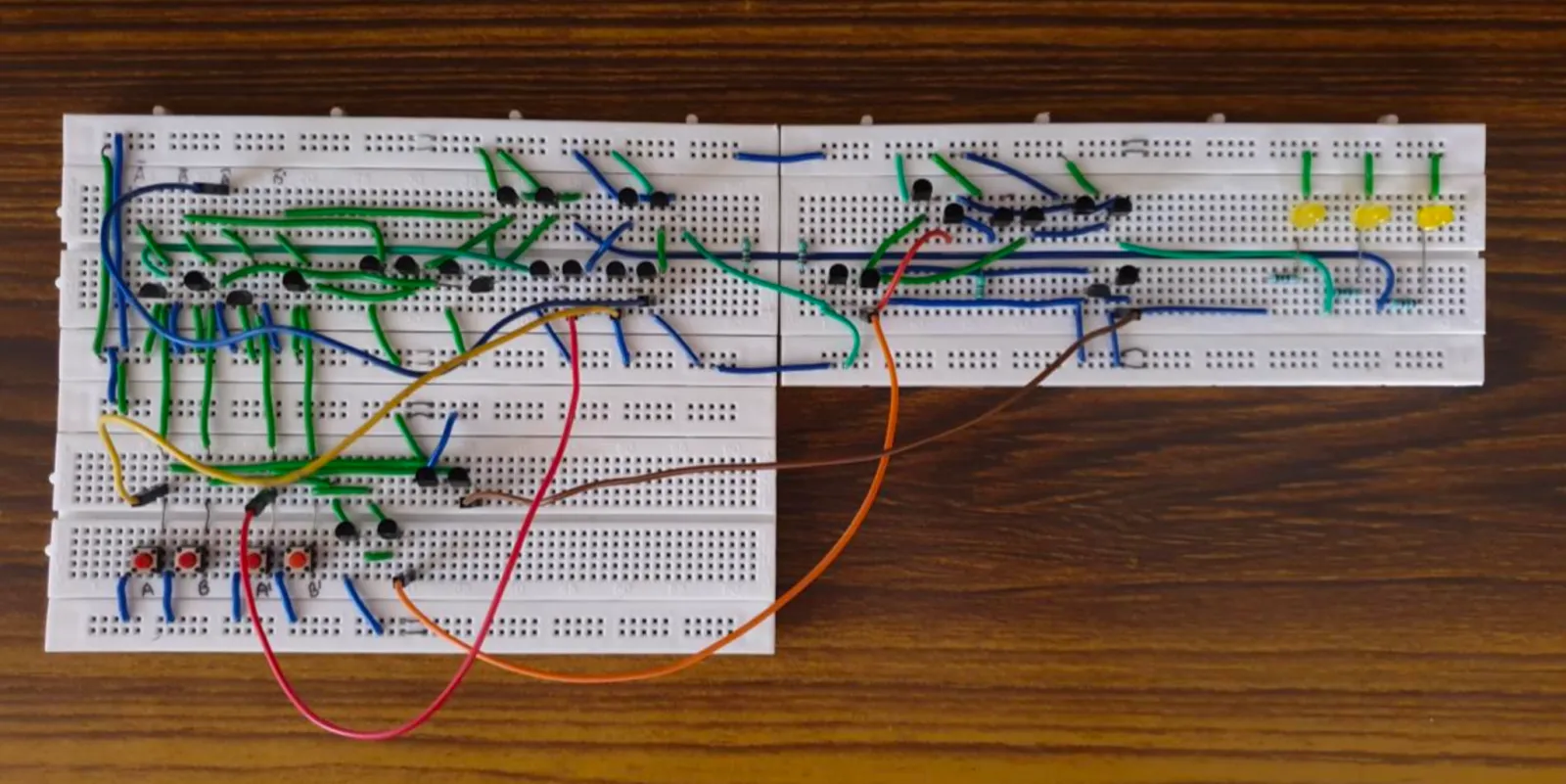
This was my high school physics project and I just DIYd it without internet or anything. Learnt about adders at first in my computer science course in std 11 and later in my physics course in std 12 (in semiconductors) so thought of implementing it in real life. I miss those days and found my report yesterday so thought of writing a blog on it. It’ll mostly be a copy of my report as I gave my all (we didn’t have ChatGPT back then) to make this. Hope this helps someone out.
Aim
To demonstrate the use of semiconductors in digital circuits by creating a binary adder that adds two 2-bit binary numbers.
Introduction
Semiconductors are materials that have conductivity between conductors and insulators. They can be pure elements, such as silicon or germanium, or compounds like gallium arsenide or cadmium selenide. Through a process called doping, adding small amounts of impurities to pure semiconductors creates large changes in the material’s conductivity.
Semiconductors are crucial to our lives through their role in electronic devices. Imagine life without electronics—no radios, TVs, computers, video games, and only basic medical diagnostic equipment. While electronic devices could be built using vacuum tubes, semiconductor technology’s advances over the past 50 years have made devices smaller, faster, and more reliable.
Materials and Equipment
Binary addition in digital circuits uses half adders and full adders. A one-bit adder consists of an XOR gate for calculating the sum and an AND gate for determining the carry. This project involves four types of logic gates: NOT, AND, OR, and XOR. These gates will be constructed using PNP transistors on a breadboard.
MATERIAL REQUIREMENTS
| Sl. No. | Item | Total | |
|---|---|---|---|
| 1. | Power Supply(5V) | 1 | |
| 2. | Breadboard | 2 | |
| 3. | 5 Ω Resistance | 3 | |
| 4. | XOR Gate | 4 | = 6 x 4 transistors |
| 5. | AND Gate | 3 | = 2 x 3 transistors |
| 6. | OR Gate | 1 | = 2 x 1 transistors |
| 7. | NOT Gate | 4 | = 1 x 4 transistors |
| 8. | M-M Connecting Wire | APR |
Theory
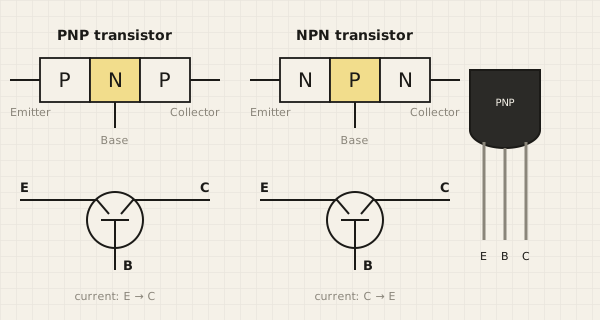
A transistor is a semiconductor device that amplifies or switches electronic signals and electrical power. It consists of semiconductor material with at least three terminals that connect to an external circuit. When voltage or current is applied to one pair of terminals, it controls the current flowing through another pair. Since the output power can exceed the input power, transistors can amplify signals. While some transistors are packaged individually today, most are embedded within integrated circuits.
A logic gate is an idealized computing model or physical electronic device that implements a Boolean function—a logical operation that takes one or more binary inputs and produces a single binary output. There are 7 basic logic gates, each performing a unique operation as shown below.
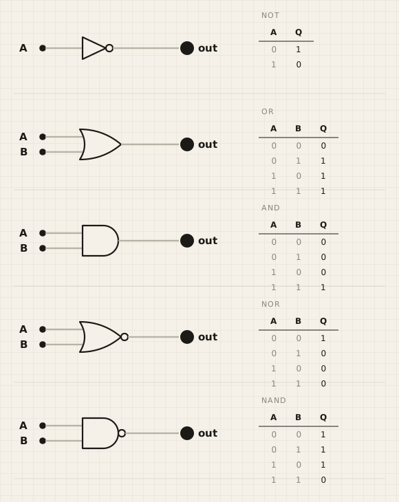
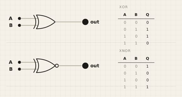
Logic gates are primarily implemented using diodes or transistors acting as electronic switches. With amplification, logic gates can be cascaded in the same way that Boolean functions can be composed, allowing the construction of a physical model of all of Boolean logic, and therefore, all of the algorithms and mathematics that can be described with Boolean logic. The binary system is a numerical system that functions virtually identically to the decimal number system that people are likely more familiar with. While the decimal number system uses the number 10 as its base, the binary system uses 2. Furthermore, although the decimal system uses the digits 0 through 9, the binary system uses only 0 and 1, and each digit is referred to as a bit. Apart from these differences, operations such as addition, subtraction, multiplication, and division are all computed following the same rules as the decimal system. Almost all modern technology and computers use the binary system due to its ease of implementation in digital circuitry using logic gates. It is much simpler to design hardware that only needs to detect two states, on and off (or true/false, present/absent, etc.). Using a decimal system would require hardware that can detect 10 states for the digits 0 through 9, and is more complicated.
Binary to Decimal
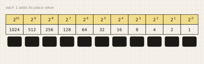
Binary addition is much like your normal everyday addition (decimal addition), except that it carries on a value of 2 instead of a value of 10. For example: In decimal addition, if you add 8 + 2 you get ten, which you write as 10; in the sum this gives a digit 0 and a carry of 1. Something similar happens in binary addition when you add 1 and 1; the result is two (as always), but since two is written as 10 in binary, we get, after summing 1 + 1 in binary, a digit 0 and a carry of 1.
| A | B | Sum | Carry |
|---|---|---|---|
| 0 | 0 | 0 | 0 |
| 0 | 1 | 1 | 0 |
| 1 | 0 | 1 | 0 |
| 1 | 1 | 0 | 1 |
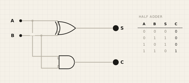
If we compare the SUM and CARRY outputs with logic gates, we see that the SUM output same as the XOR gate output and the CARRY output is same as the AND gate output.
Procedure
Transistors are commonly used in digital circuits as electronic switches which can be either in an “on” or “off” state, both for high-power applications such as switched-mode power supplies and for low-power applications such as logic gates.
To create a two-bit Adder, we will require a half adder (to add the first bit and generate its carry) and a Full adder (to add the next bit and generate its carry and use the previous bit carry) to give the final three bit binary output.
For example: If we have two binary number 10 and 11, the addition will take place in the following way:
Let 10 be A and 11 be B. First 1st bit of both A and B will undergo binary addition (0 + 1 = 1) giving 0 carry. Then the carry will go for the next bit addition. The addition will take place as follows (1 + 1 + 0 = 0) with carry 1. Therefore the final output would be 101.
Half adder schematic
Full Adder schematic
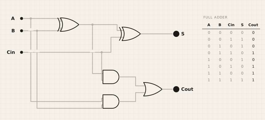
The carry© from the half adder would go to the (Cin) in the full adder. S in half adder will give the sum of 1st bit. The S of the Full adder will give the 2nd bit and the Cout will give the final bit.
Final circuit schematic
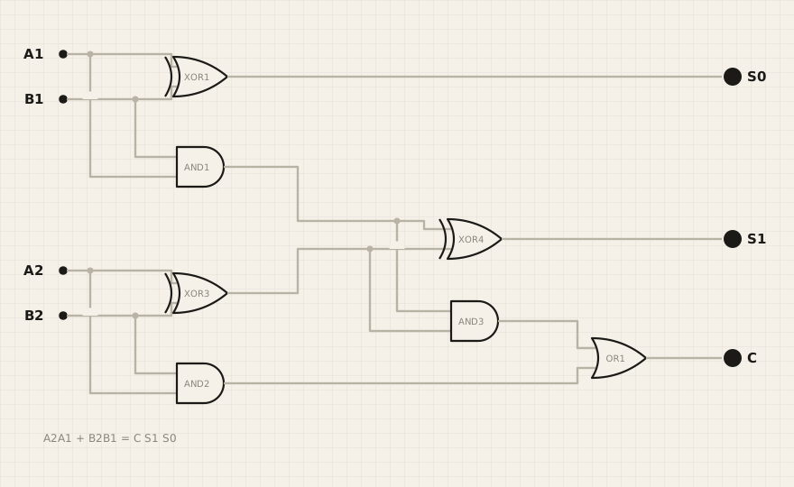
The final schematic contains 3 XOR gates, 3 AND gates and 1 OR gate. And we will also require 4 NOT gates. Since we have to use PNP-transistors, we would have to convert each gate into transistor schematic.
NOT Gate using PNP transistor(s):
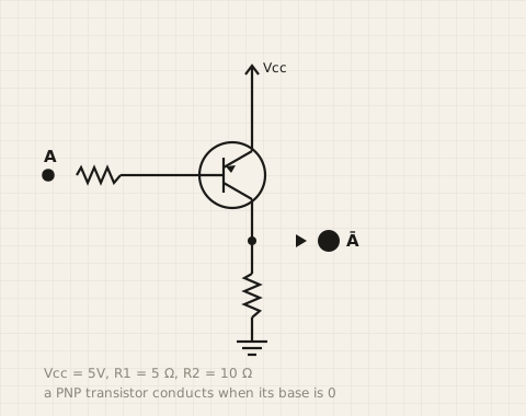
Vcc = 5V, R1 = 5 Ω, R2 = 10 Ω
AND Gate using PNP transistor(s):
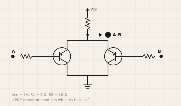
Vcc = 5V, R1 = 5 Ω, R2 = 10 Ω
OR Gate using PNP transistor(s):
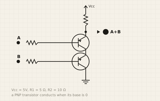
Vcc = 5V, R1 = 5 Ω, R2 = 10 Ω
XOR gate, as we can see in the schematic below, is just a combination of AND, OR and NOT gates.
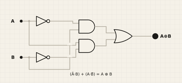
So, we will use them to get the XOR output.
Calculations
We have already created the digital schematic of the circuit. Let’s calculate the Boolean expressions for each logic gate to help us understand the circuit better:
- XOR1 Output:
(A1)'.(B1) + (A1).(B1)' - AND1 Output:
(A1).(B1) - XOR3 Output:
(A2)'.(B2) + (A2).(B2)' - AND2 Output:
(A2).(B2) - AND3 Output:
(AND1).(XOR3) = (A1).(B1).(A2)'.(B2) + (A1).(B1).(A2).(B2)' - XOR4 Output:
(AND1)⊕(XOR3) = ((A1).(B1))'((A2)'(B2)+(A2)(B2)') + ((A1).(B1))((A2)'(B2)+(A2)(B2)')' - OR1 Output:
(AND3)+(AND2) = ((A1).(B1).(A2)'.(B2) + (A1).(B1).(A2).(B2)') + ((A2).(B2))
Result
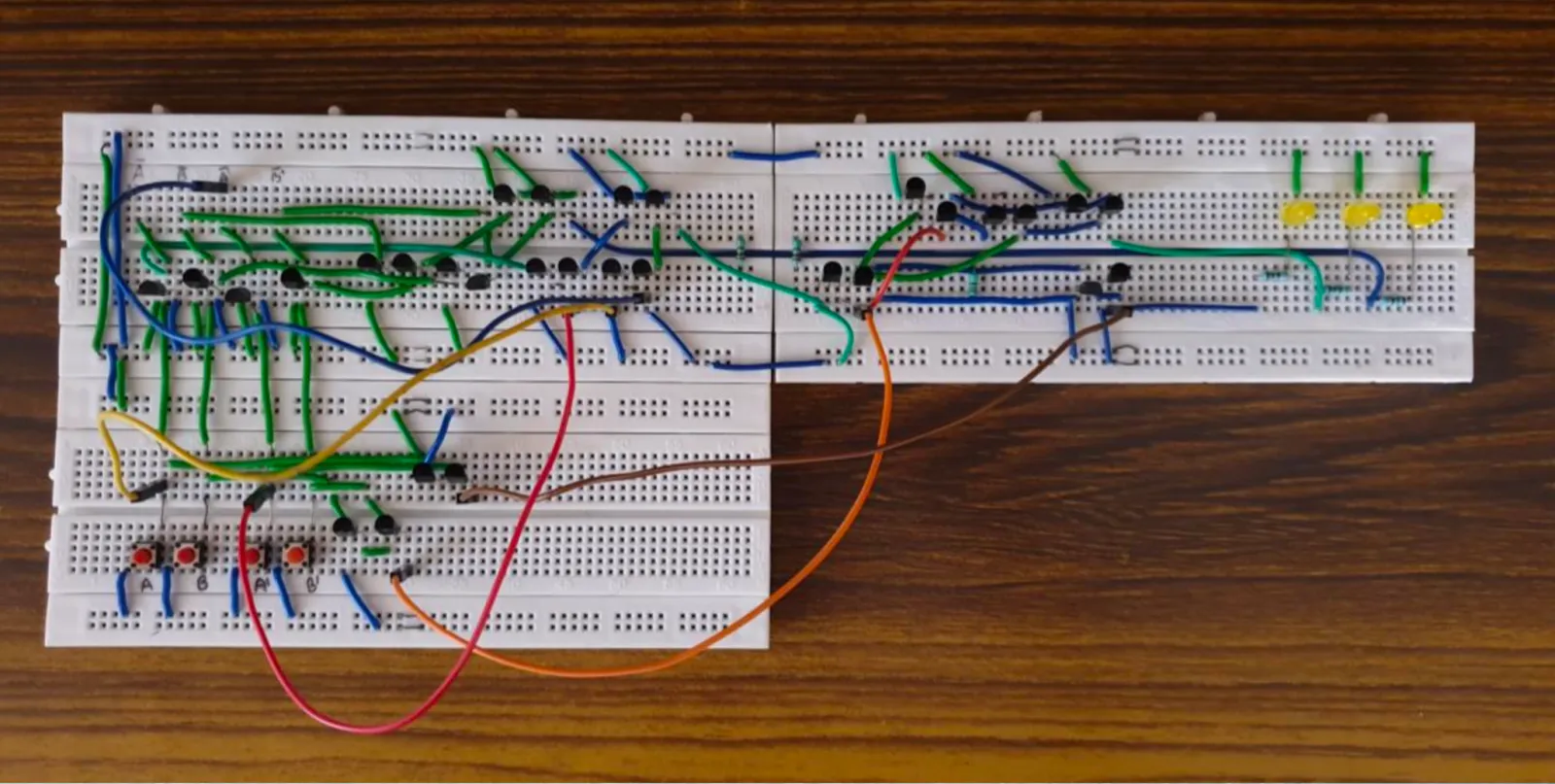
Here is the final circuit created which calculates the sum of two 2-bit binary numbers.
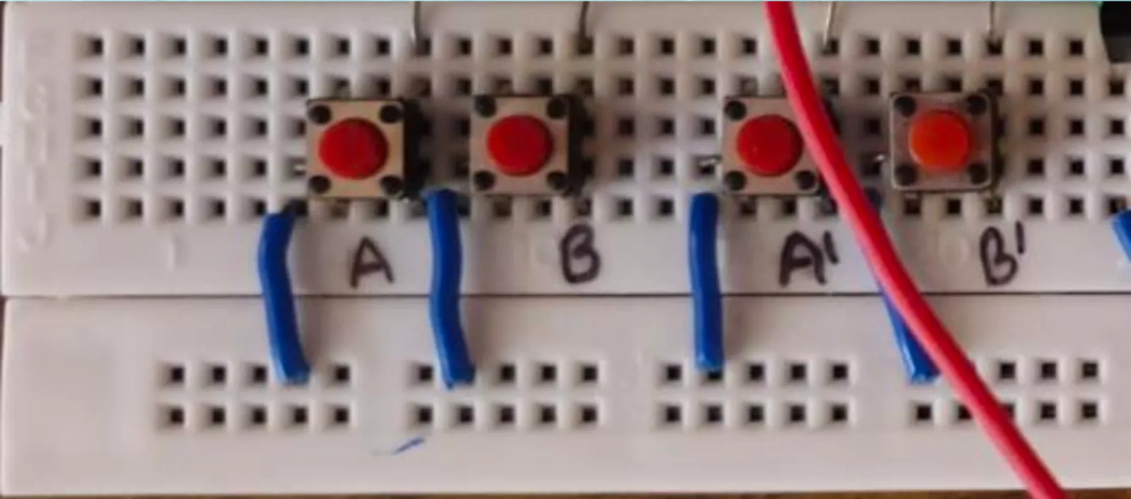
The 4 push buttons present at the bottom left side of the circuit board allow us to control the state of the bits.
The number input goes as follows:
1st Number – AB (where A and B are the bit values of the numbers)
2nd Number – A’B’ (where A’ and B’ are the bit values of the numbers)
Pressing the push button changes the bit value to 1, else it remains 0.
For example, if we want to add 10 and 11, we will press A, A’, and B’.
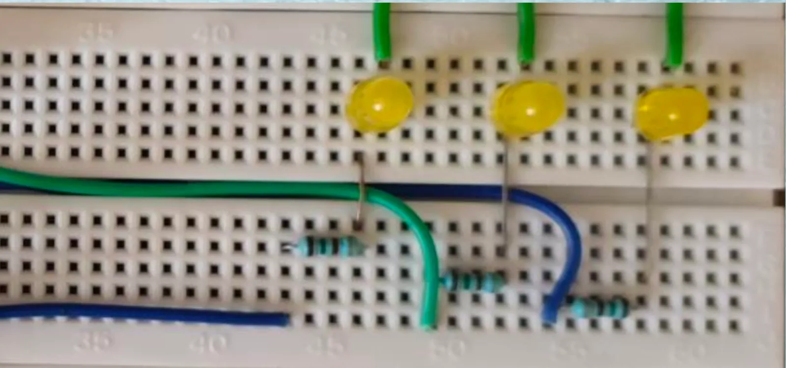
The output is displayed using 3 LED lights. For example, if the input is 10 and 11, the output should be 101. In that case the 1st and the 3rd light will glow(On indicates 1).
Conclusion
It’s impossible to overstate the impact that personal computing has had on our modern world, and all of that innovation is only possible due to the invention of the transistor. The invention of transistors ignited a series of changes and advances that would change the way people listen to their favorite music, do their jobs, pay their bills, educate themselves and buy everything from books to used toaster ovens.
Transistors inside pacemakers keep our hearts going. Computer chips run inside our cars, cell phones, and even tiny, implantable LoJack-like devices that help find lost pets. The PC and the Internet have been phenomena, but how usable and ubiquitous would they be without millions of tiny transistors running inside laptops, desktops, and servers?
It’s tough to say whether it was the most important invention in human history, but it definitely completely changed the world.
Precautions
- You may nip off the component leads appropriately so that they do not fit clumsily.
- While breadboarding a circuit, the component distributions may not be that critical, but their positioning will definitely require serious attention.
- The signal input and the output of the circuit should be directed towards the left and the right hand side of the board respectively.
- Do not apply mains voltages directly to the breadboard circuitry because again the closely situated connections may possibly create arcing or even dangerous short circuits and a fire.